這一周我們要給各位認識的是 Serial Communication ,也就是串列通訊。
通訊在嵌入式系統中是非常重要的功能,原因除了要與其他設備交換資料之外,還有在 Debug 時所能提供的資料遠比只用 LED 來做 Debug 來得好很多。
當然,更好的 Debug 方式是使用專用的 Debugger 與軟體來做,但在軟硬體較為欠缺的時候,利用預先寫在晶片中的程式輸出一些資訊來了解系統運作是較好的選擇。
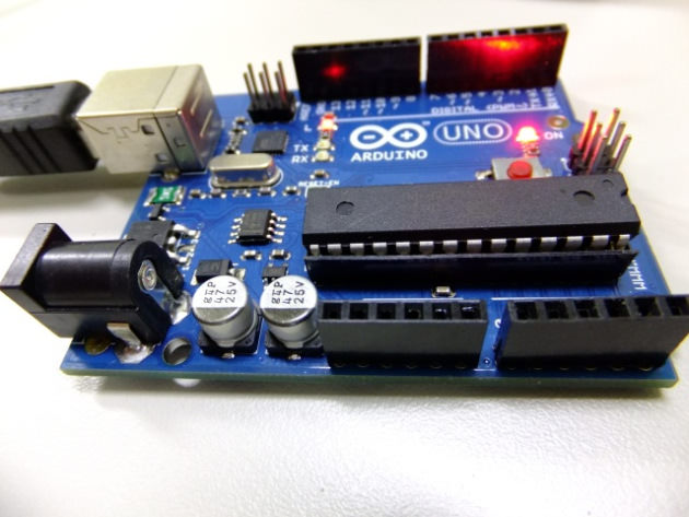
在 Arduio 系列中提供至少一組可直接與電腦透過 UART (RS232)交換資料的通訊介面,只要 Arduino 有跟電腦透過 USB 連線且安裝驅動程式,便會產生一個 COM Port 以便通訊用。
基本語法
啟用串列通訊的方式要先在 setup() 中加入
|
1 2 |
Serial.begin(9600); |
這段程式碼,才會啟用預設且與電腦通訊的那組 UART 通訊介面,其中的9600是齙率,可用的值如下:
- 300
- 600
- 1200
- 2400
- 4800
- 9600
- 14400
- 19200
- 28800
- 38400
- 57600
- 115200
傳送資料
當你要將資料傳速出去時,你必須用如下的指令來傳輸
|
1 2 3 4 5 6 7 |
// 不自動斷行的 print Serial.print("字串內容"); // 會自動斷行的 print Serial.println("字串內容"); // 傳遞數值 Serial.print(變數); |
要注意的是,Arduino 並沒有提供如 C 語言中的 printf() 函式,且也不支援類似 Java 中以 + 號連接字串的方式,因此無法只用一個 print 來傳遞所有要傳輸的內容。當你有一串內容要傳輸時,請利用如下的方式來傳:
|
1 2 3 4 5 |
Serial.print("Value: "); Serial.print( 變數 ); Serial.print(" Value 2: "); Serial.print( 變數2 ); |
接收資料
當你需要接收來自電腦(或其他藉由 UART 介面通訊的周邊)時,你就會用到read()這個函式。
|
1 2 |
char c = Serial.read(); |
與電腦溝通
程式碼
|
1 2 3 4 5 6 7 8 9 10 11 12 13 14 15 16 17 18 19 |
char incomingChr = 0; // 存放讀到的資料 void setup() { Serial.begin(9600); // 以 9600 的齙率啟用 UART 串列傳輸 } void loop() { // 當有資料進來時才傳送資料出去 if (Serial.available() > 0) { // 讀取收到的資料 incomingChr = Serial.read(); // 回傳收到的內容 Serial.print("我收到了: "); Serial.println(incomingChr); } } |
燒錄好程式,然後選擇 Tools -> Serial Monitor 便有一個可與 Arduino 透過 UART 通訊的終端機,當你發送資料時,畫面就會顯示你發送的內容。
控制 LED
程式碼
|
1 2 3 4 5 6 7 8 9 10 11 12 13 14 15 16 17 18 19 20 21 22 23 |
int led = 13; // 板子上的 LED char incomingChr = 0; // 存放讀到的資料 void setup() { Serial.begin(9600); // 以 9600 的齙率啟用 UART 串列傳輸 } void loop() { // 當有資料進來時才傳送資料出去 if (Serial.available() > 0) { // 讀取收到的資料 incomingChr = Serial.read(); // 當 Arduino 收到字元 L 後,會讓 LED 亮起 0.5 秒 if( incomingChr == 'L' ) { digitalWrite(led, HIGH); delay(500); } } } |
軟體 RS232
Arduino UNO 在硬體上僅有提供一組 UART 通訊界面,在一些應用上會顯得有些不足,所以就有人寫了一個軟體版本的 Serial 介面來做擴充。
要注意的是,因為試用軟體的方式來做串列通訊,因此在baud rate上不建議設定超過 9600。
範例程式
來源: https://www.arduino.cc/en/Tutorial/SoftwareSerialExample
|
1 2 3 4 5 6 7 8 9 10 11 12 13 14 15 16 17 18 19 20 21 22 23 24 25 26 27 28 29 30 31 32 33 34 35 36 37 38 39 40 41 42 43 44 45 46 47 48 49 50 51 52 53 54 55 |
/* Software serial multple serial test Receives from the hardware serial, sends to software serial. Receives from software serial, sends to hardware serial. The circuit: * RX is digital pin 10 (connect to TX of other device) * TX is digital pin 11 (connect to RX of other device) Note: Not all pins on the Mega and Mega 2560 support change interrupts, so only the following can be used for RX: 10, 11, 12, 13, 50, 51, 52, 53, 62, 63, 64, 65, 66, 67, 68, 69 Not all pins on the Leonardo support change interrupts, so only the following can be used for RX: 8, 9, 10, 11, 14 (MISO), 15 (SCK), 16 (MOSI). created back in the mists of time modified 25 May 2012 by Tom Igoe based on Mikal Hart's example This example code is in the public domain. */ #include <SoftwareSerial.h> SoftwareSerial mySerial(10, 11); // RX, TX void setup() { // 這是啟動與電腦通訊用的串列通訊,就是原生那組 Serial.begin(57600); while (!Serial) { ; // wait for serial port to connect. Needed for native USB port only } Serial.println("Goodnight moon!"); // 設定軟體 Serial Port 的 baud rate 為 4800 mySerial.begin(4800); mySerial.println("Hello, world?"); } void loop() { // run over and over if (mySerial.available()) { Serial.write(mySerial.read()); } if (Serial.available()) { mySerial.write(Serial.read()); } } |
到此,我們把基本的串列通訊方式介紹完了,如果你需要更詳細的介紹與使用方式,可以參考官方網站的內容。
